1.9 m × 2.4 m Cathodic Arc PVD Machine — Engineering Documentation
Complete vacuum, electrical, oil, cooling water, and operational reference for the Shenyang Youbida KT-1200 diffusion pump system, 2 × 7.5 kW Roots, 6 × 70 L/s (5.5 kW) Rotary Vane pumps, and 22 × SASH Arc Sources.
Chamber Volume
Ø1.9m × 2.4m (6.8 m³)
Diffusion Pump
KT-1200 (50,000 L/s)
Oil Charge
22 L HFV-K3 (230–260°C)
KT-1200 Heater
24 kW (~36.5 A / ph)
Cooling Water
40–50 LPM (Min 35)
Time to 1.0×10⁻² Pa
~15–22 min (Hot)
1. Full Vacuum, Gas & Arc System Architecture
Interactive schematic matching your pit layout, Samkoon HMI (2组 dual backing groups), and 22-source SASH cathodic arc rack.
2. KT-1200 External, Internal & Machine Spec Placard
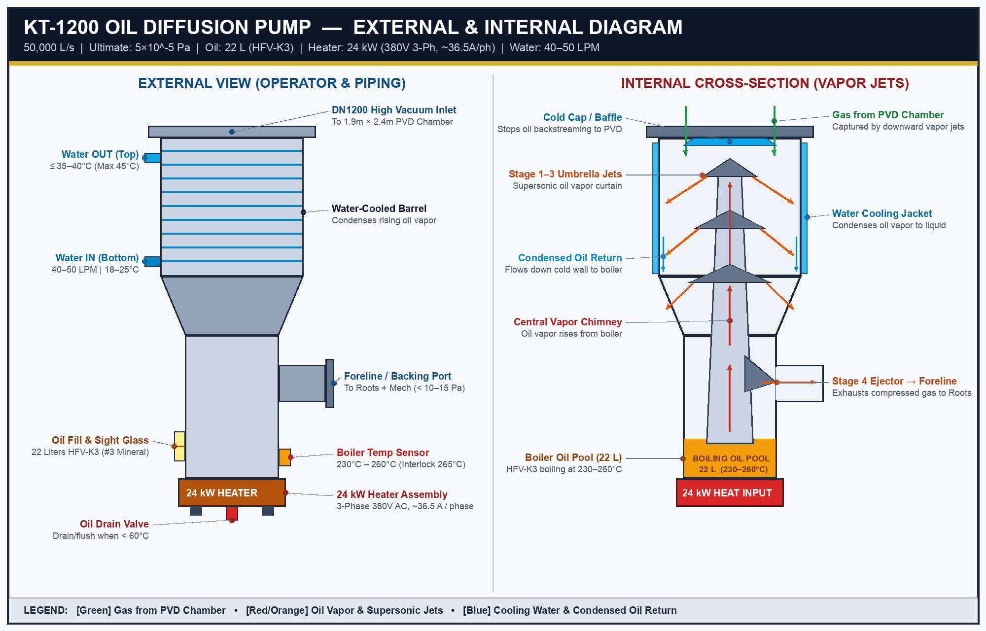
External Piping & Internal 4-Stage Jet Cross-Section
Download PNG
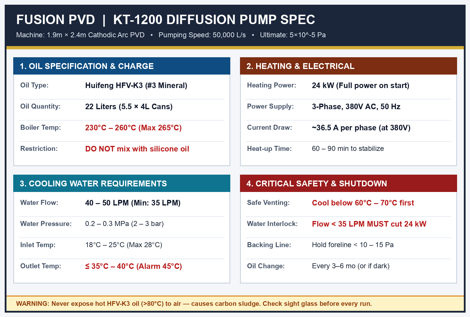
Print-Ready Machine Spec Sticker (300 DPI)
Download PNG
3. Pump-Down Curve to 1.0 × 10⁻² Pa (6.8 m³ Chamber)
| Stage | Pressure Range | Active Pumps | Est. Duration (Hot Pump) |
|---|---|---|---|
| 1. Roughing | 100,000 Pa → 2,000 Pa | 6 × 70 L/s Rotary Vane (420 L/s) | ~1.5 – 2 min |
| 2. Roots Booster | 2,000 Pa → 5 Pa | 2 × 7.5 kW Roots + 6 × Rotary (~1,200 L/s) | ~5 – 8 min |
| 3. Diffusion Pump | 5 Pa → 1.0 × 10⁻² Pa | KT-1200 (50,000 L/s, High-Vac Valve Open) | ~8 – 12 min (outgassing dependent) |
4. Electrical Load & 24 kW 3-Phase Heater Plate Diagram
Total vacuum train load is 72 kW (~124.5 A / phase at 380V) excluding chamber heaters and the 22 SASH arc sources.
5. Cooling Water & HFV-K3 Oil Management
| Parameter | Specification | Critical Limit / Action |
|---|---|---|
| Oil Type & Charge | Huifeng HFV-K3 (#3 Mineral) — 22 Liters (5.5 × 4 L cans) | Do NOT mix with silicone oil (275# / DC-704). Change every 3–6 months. |
| Boiler Temp | 230°C – 260°C | Over-temp cutoff at 265°C. Cool < 60–70°C before venting/shutdown. |
| Water Flow Rate | 40 – 50 LPM (2.4 – 3.0 m³/h) | Minimum 35 LPM; flow switch must trip 24 kW heater below 35 LPM. |
| Water Temp & Pressure | Inlet: 18–25°C | Pressure: 0.2–0.3 MPa (2–3 bar) | Outlet must stay ≤ 35–40°C (Alarm at 45°C). |
6. Operating SOPs & Interactive Pre-Start Checklist
7. Site-Specific Inspection Findings (From Your Photos)
1. Cracked Top Ceramic Sector on 24 kW Heater Plate: Verify coil-to-pan insulation (MΩ), balance all 3 phase resistances (~6.05 Ω Star / ~18.05 Ω Delta), and replace oxidized terminal ceramic beads before reassembly.
2. Delta Temp Controller Showing
PV: no: Thermocouple is open/disconnected on the front panel unit. Confirm which controller drives the KT-1200 boiler SSR/contactor before powering the 24 kW heater.
3. Purple uPVC Exhaust Manifold & Cabinet Wiring: Ensure purple uPVC exhaust header is ≥ DN100 (110 mm) with an oil-drain trap for the 420 L/s combined rotary exhaust, and bundle loose red wires inside the Siemens PLC / Schneider relay cabinet.